Build Instructions
Assembly Overview
Building the OpenTholoMetri takes a couple of hours, spread across a few days. Follow these steps carefully to ensure proper operation.
0: Order parts
If you have not already, order the parts listed out in the BOM. If you have everything ready including the tools, follow the guide below :)
1: Soldering
If you don't have much experience soldering, start with the easier parts, like the individual wires. A connection diagram can be found below:
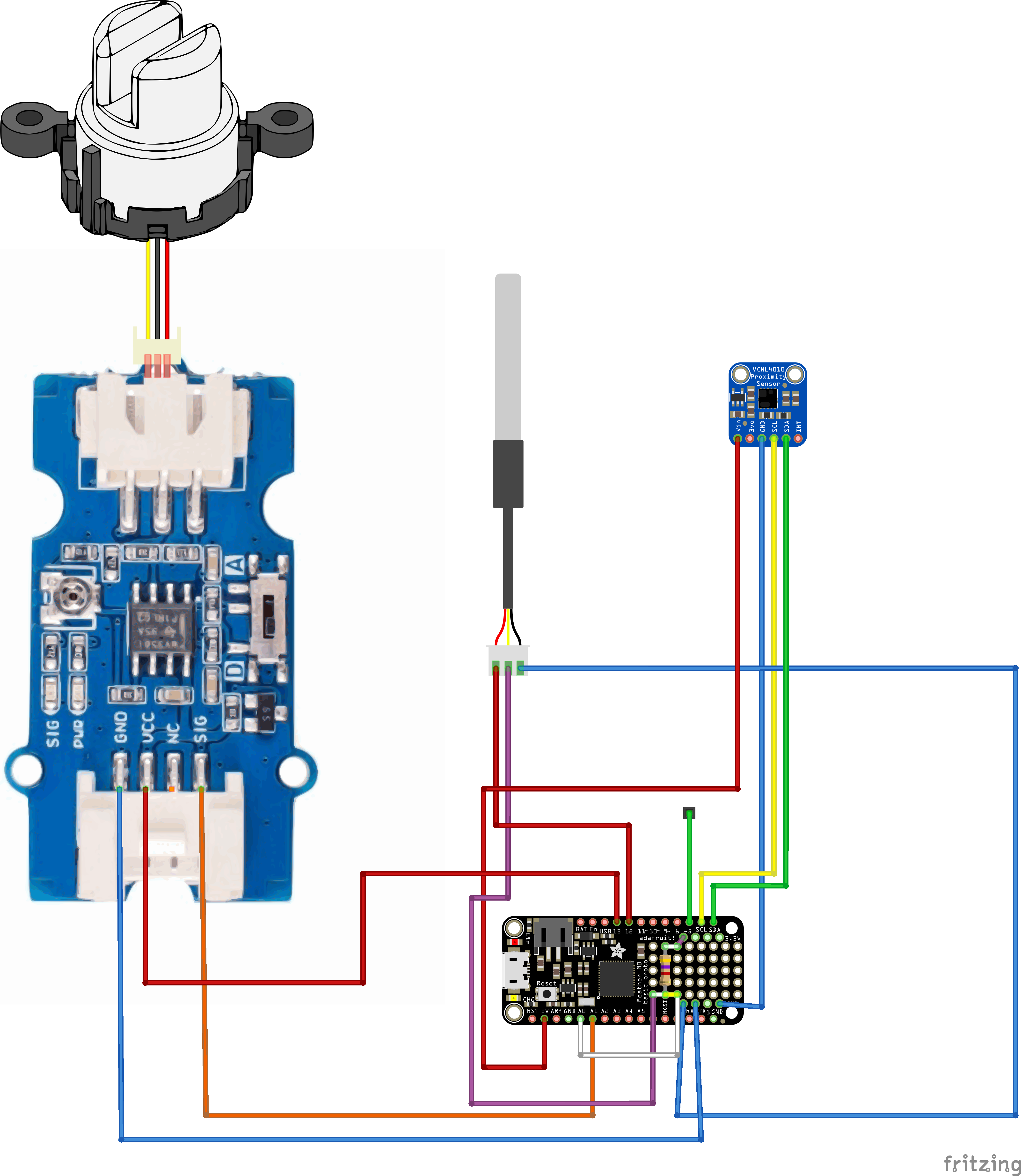
Solder the individual connections to the Adalogger's second set of pins. The first set is used for the headers to connect the Adalogger to the Feather M0.
2: 3D printed housing
3D print the housing from the STEP file provided here. You can use any 3D printer; be sure to turn on supports if needed for your printer.
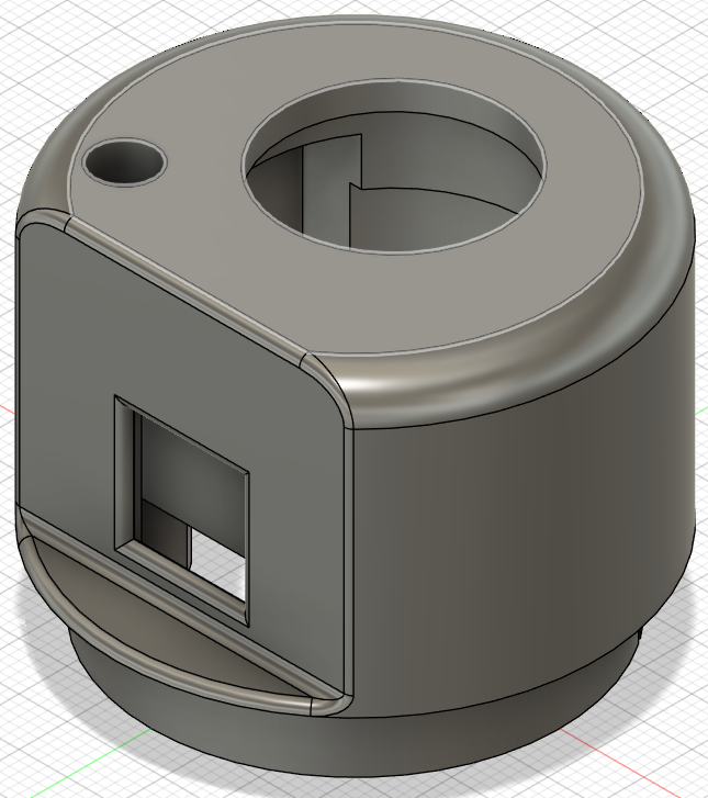
3: Fitting sensors in housing
Fit the Grove turbidity sensor first, then push in the VCNL4010 and finally fit the DS18B20 probe.
4: Pouring the epoxy in the housing
This step takes by far the longest. I did it with two sets of epoxy. The first one is a quick-set epoxy that I used to mount everything; the second is a slow-setting epoxy that is easy to use for this case because it's not very viscous, which means it doesn't need a vacuum pump to be clear.
When pouring the final epoxy, make sure the sensor is lying flat. It might need to be poured in two layers due to the epoxy leaking out.
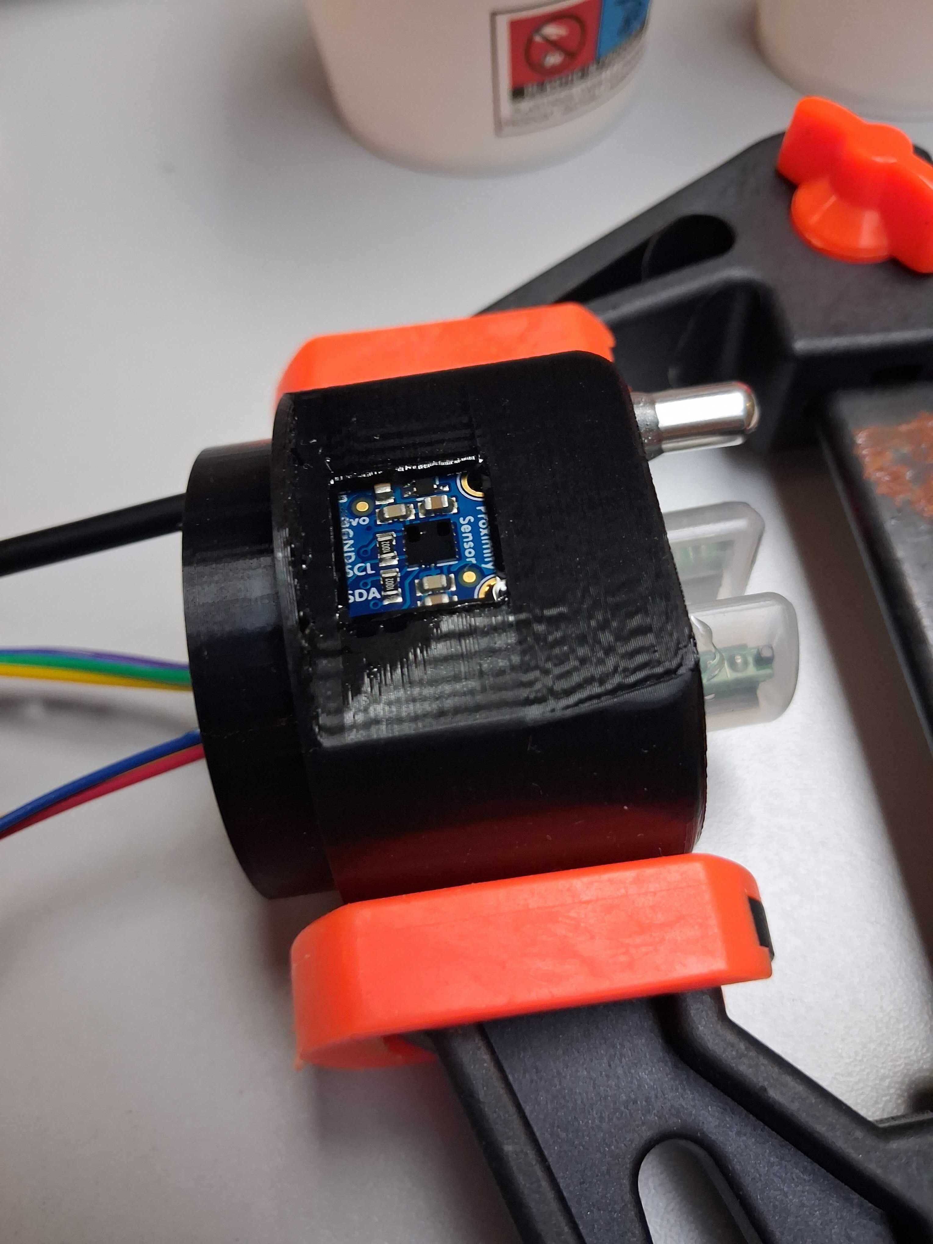
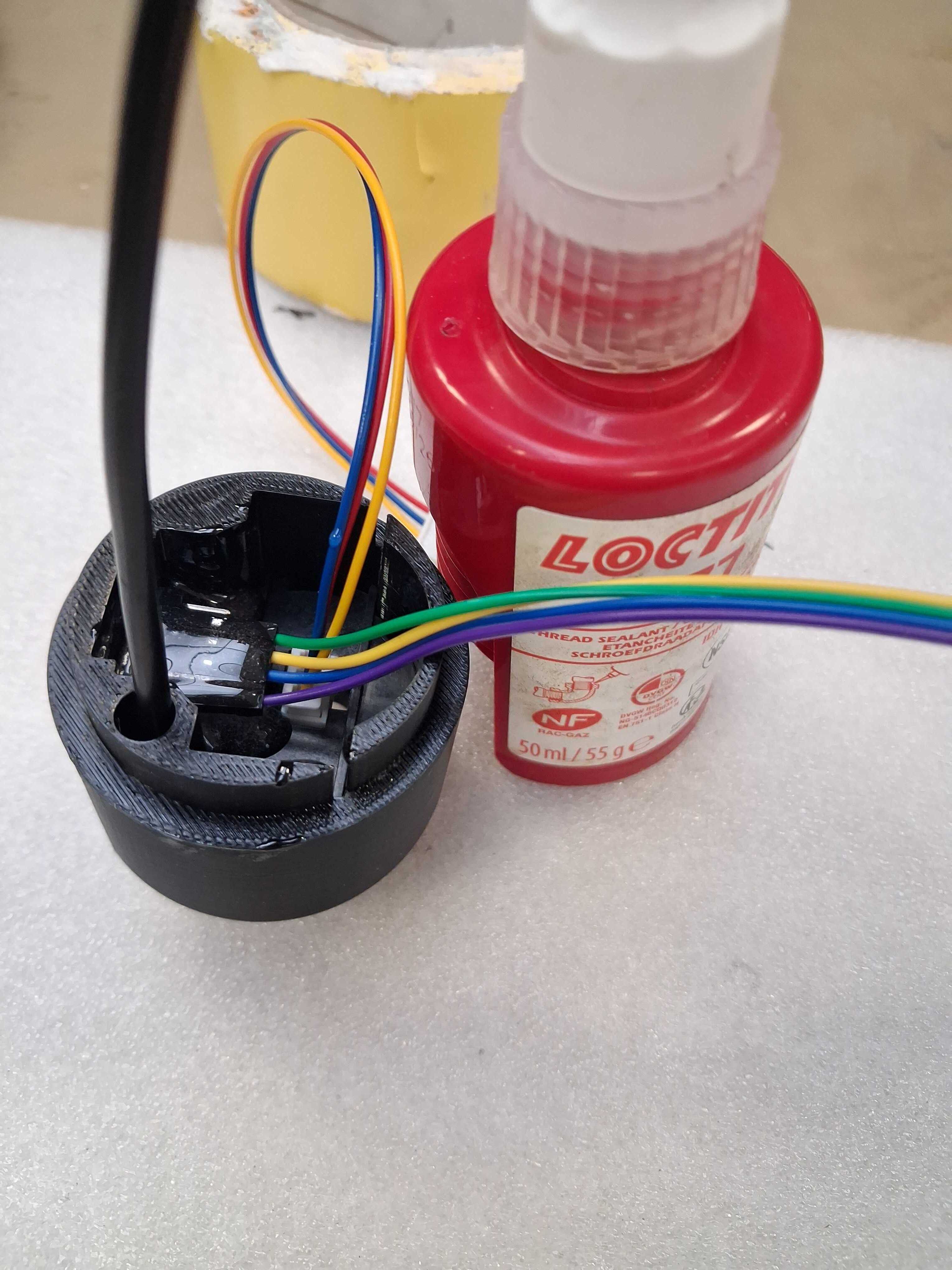
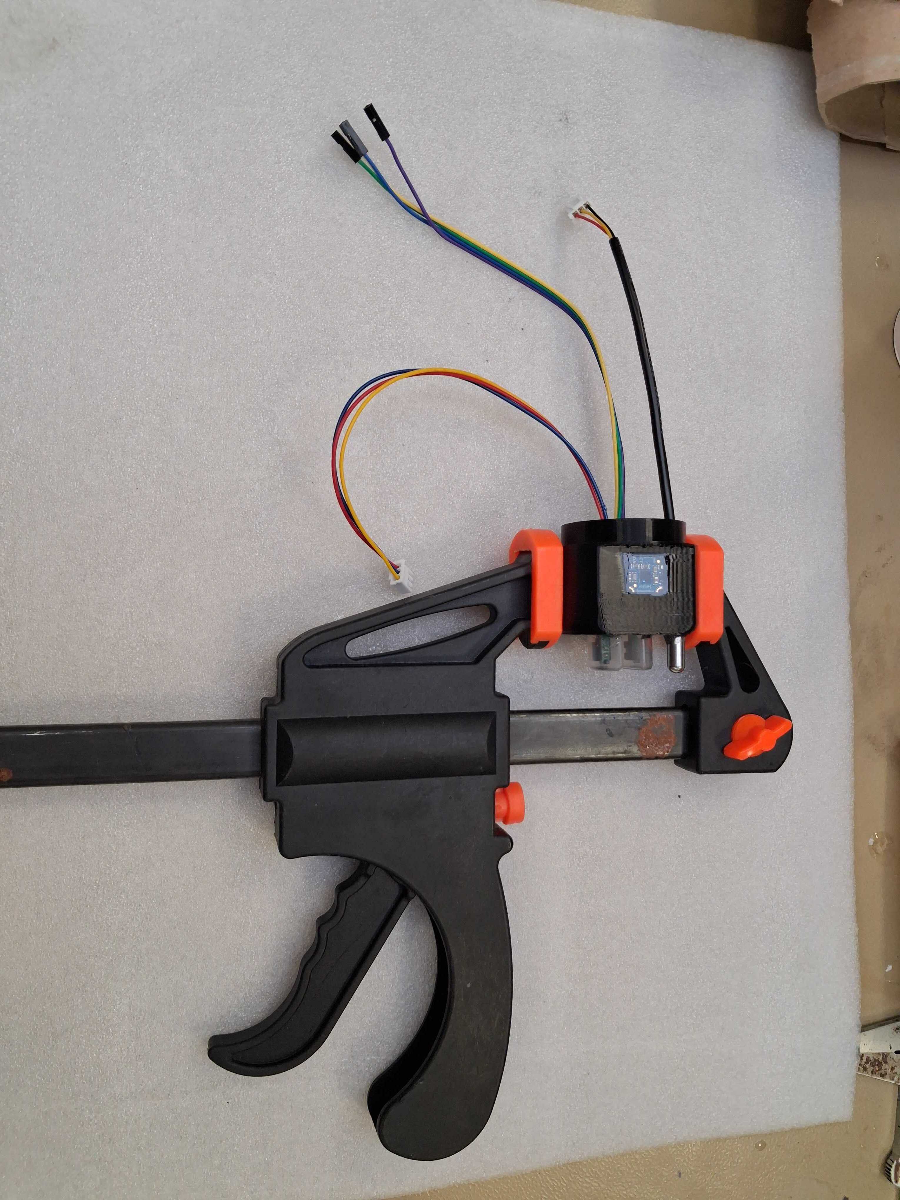 The picture above is from the first prototype, don't worry about the connections.
5: Uploading the firmware to the board
Plug in the board via USB to your computer, then double-click the button on the board (M0). The light will start pulsing and a new USB drive will appear; copy the .uf2 file found here. This is the firmware with default settings. If you want to change these, you will have to recompile the firmware; see the firmware guide.
6: Fitting the head to the tube
Put the boards and wires in the tube, fit the 3d print in the tube, next pour in the expoxy untill the head is sealed.
Make sure to let this epoxy harden fully, because this provides a final seal between the head and tube, protecting the board inside.
7: Closing the tube
Finally, fit the cap with pvc glue and close it with teflon to be waterproof.
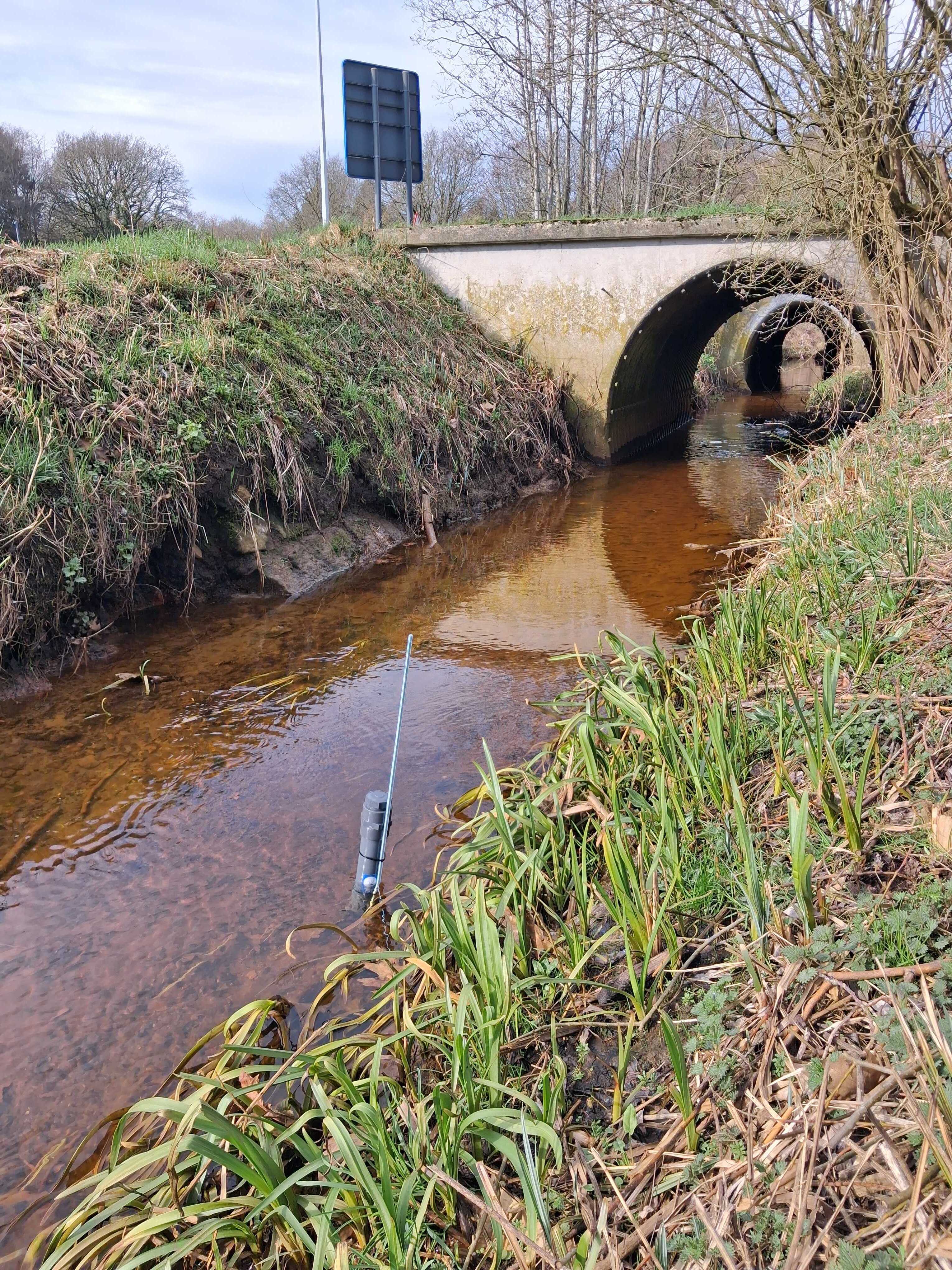
8: Deploy
Charge the boards battery with the USB port and install the sensor at the wanted location.